RadioPropagation
It is well known that attenuation of radio signals depends heavily on the terrain and other physical obstacles encountered between transmitter and receiver. This component, making use of the elevation data available in MariaGDK, aims to identify the characteristics of such obstacles and calculate predictions of radio connectivity and coverage across a geographic area of interest. The calculation models, as described below, span from the simple line-of-sight approach (which roughly applies to radio communication at the higher ranges of the UHF band and beyond) to the more complex ones taking the property of microwave diffraction at lower frequencies into account.
Calculation models
RadixMKE
The model calculates predicted signal strength in dBm due to path loss of microwave radiation from diffraction over multiple knife-edge obstacles - using the Deygout (1966) step-by-step approach. The method, which avoids the necessity of evaluating the Fresnel integral at each steep, has been shown to give fairly accurate predictions (+- 3dB) for the VHF- and the lower ranges of the UHF band along mixed/mountainous propagation paths.
Parameters: Frequency, TxHeight, RxHeight, Polarization, Refraction, TxPower, TxGain, RxGain
VHF/UHF
This is a somewhat modified implementation of Deygout's diffraction model, with the additional possibility to limit the number knife-edges to the n most significant.
Parameters: Frequency, TxHeight, RxHeight, Polarization, Refraction, NumberOfKnifeEdges, TxPower, TxGain, RxGain.
VHF/UHF (ITU529)
This is an implementation of the ITU 529 recommendation for calculating path loss across moderate ranges (3-15 km) for radiations in the VHF-UHF bands under "average" obstacle conditions using the Okumura-Hata equations.
Parameters: Frequency, TxHeight, RxHeight, Polarization, TxPower, TxGain, RxGain.
Air Search Radar
Calculates the minimum height (ASL) of any target to be visible at that location from a fixed observer point.
Parameters: TxHeight, RxHeight, Refraction.
Freesight
Determines visibility of any ground level (+ RxHeight) target at its current location from a fixed observer point.
Parameters: TxHeight, RxHeight, Refraction.
Simple code example
The calculation methods are accessible through the IRadioPropagationProvider interface. The below code is a very simple example showing how to use the Air Search Radar model, with default parameter settings only - except for the position of the observer. Apart from the IRadioPropagationProvider, the example also introduces the IRadioPropagationLayer and ITransmitterReceiver interfaces, all of which will be discussed more comprehensively below.
IElevationDataInterfacer _elevationInterfacer;
IMapResources _mapResources;
//
// Both _mapResources and _elevationInterfaces assumed initialised.
// Pass those parameters to construct the one and only RadioPropagtionProvider object.
//
IRadioPropagationProvider _radioPropagationProvider = new RadioPropagationProvider(_elevationInterfacer, _mapResources, null);
//
// Construct a layer to contain a set of radio units or points of observation, with capabilities to draw coverage charts.
// Add that layer to the provider.
//
IRadioPropagationLayer layer = new RadioPropagationLayer("Some_layer_name");
_radioPropagationProvider.AddLayer(layer);
//
// Select a calculation model, and assign it to the layer
//
var model = _radioPropagationProvider.GetModelByName("Air Search Radar");
layer.Model = model;
//
// Assign a legend, compatible with the selected model
//
layer.Legend = model.LegendInfo;
//
// Set pixel resolution, in meters - if anything other than default (=270.0) is desired.
//
layer.Resolution = 90.0;

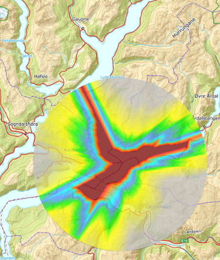
//Deploy a radio unit or point of observation, here chosen at the confluence of Lusterfjorden and Årdalsfjorden

var u = new TransmitterReceiver(new GeoPos(61.18, 7.42));
layer.AddUnit(u);

u.Calculate();
With (mostly) default parameter settings, a raster chart representing the calculation result will appear as shown:
RadioPropagationProvider
Apart from serving as a common access point to calculation models along with the necessary elevation data on which these methods depend, it may be deduced from the simple code example above that the RadioPropagationProvider also is a container for layer objects compatible with the IRadioProgationLayer interface. In turn these layers are containers for objects compatible with the ITransmitterReceiver interface, designating single radio units or points of observation. These relations just about describe the main object hierarchy within the RadioPropagation component. Units belonging to the same layer may contribute to the allover "coverage" across a common geographical area. Such a collection of units also define a network for which mutual connectivity may be investigated, provided this concept makes sense given the model in question.
The RadioPropagationProvider is also a container for registered Antenna Patterns. These are equipment specific and may be shared freely between units.
RadioPropagationLayer
The term "Layer" ending the type name stems from it representing a separate raster layer for drawing of its coverage chart. This chart will by default indicate the allover coverage from all participating units. To show contribution from one or a subset of units only, the Visible property for all other units in that layer must be turned off.
Naturally all units within the same layer use the same calculation model, along with the same model specific parameters. This makes it convenient to set these for the layer as a whole, rather than for each unit individually.
Changing any of these parameters, a recalculation is required for coverage results to be compatible.
Refraction
Earth radius along elevation profiles are inflated to account for atmospheric refraction. Default value of this parameter is 4/3.
Frequency
Carrier mean frequency in MHz of a transmitted signal. All radio units within a layer operates on the same frequency unless explicitly overridden. To do so for any single unit, simply set its frequency to the desired value. This value should preferably be set within in the VHF (appr 30MHz - 300MHz) or the lower part of the UHF ranges (appr 300MHz-3000MHz). For higher frequencies, wave diffraction around main obstacles is far less likely to occur, propagation generally limited to line-of-sight, attenuated by free space loss.
Polarization
Wave polarization, 1 = vertical, 0 = horizontal.
RxHeight
Receiver antenna height above ground level in meters. This height should not erroneously be mixed up with the receiver antenna height for individual radio units. It is meant for coverage calculations only, where a "virtual" receiver may be thought to be deployed anywhere and everywhere within the geographical area being examined.
It should be noted that this parameter is taken into account also when using a "passive" calculation model - e.g. Freesight. The effect in that case is simply that a potential target is thought to be elevated above ground level accordingly - and may then be visible for that reason alone.
RxGain
Antenna receiver gain, nominal or peak value in dB for coverage calculations. For this purpose, as with RxHeight as a layer parameter, the receiver is "virtual". The antenna may well be thought to be directional - and still optimally adjusted to concentrate signals from all directions simultaneously, something which naturally would be unattainable in practice.
NumberOfKnifeEdges
Max number of diffraction knife-edges. VHF/UHF model only. Default = 3.
Resolution
The Resolution property is the pixel size in meters of a coverage chart. It also affects the effective step length used in calculations when tracing an elevation profile between any two single points. Compatibility between units within a layer is the reason why this property is set for the layer as a whole, not for individual units separately - although the latter could have been a possibility.
These parameters affects presentation or interpretation only, and do not require any new (re)calculation.
Legend
The color legend used to draw the coverage chart. It is of type CoverageLegendInfo, basically a list of items, of which each assigns a color to some subinterval of the range of whatever value the calculation model produces. These subintervals should be concecutively ordered, but do not need to be contiguous, nor span the entire value range.
It is necessary to use the _set_ method, for any changes to take effect.
Transmitters and Receivers
Dependent on the calculation model, a TransmitterReceiver object, see ITransmitterReceiver may denote a radio unit with capabilities for up- and downlink communication or, in its simplest form, a point of observation. In addition to a given position, every such object has a geographical area attached. This area does not necessarily coincide with or even indicate the extent of any actual coverage. It just defines the area for which coverage predictions will be made. Nor does it necessarily include the location of the unit itself. By default, however, it is so. Unless otherwise specified, it is initially defined as the region within 16000 meter from the unit position.
Additional parameters for TransmitterReceiver objects, available through the ITransmitterReceiver interface, include the option for setting individual frequency, emitted signal power and antenna characteristics - azimuth, tilt and gain distribution.
Coverage Area Types
The alternatives available to define a coverage area, other than the one assigned by default, are:
| AreaType | Description |
|---|---|
| AreaGeoRect | Coverage area is a geographical rectangle, possibly not including the unit position, and does not change if unit position changes. |
| AreaRoute | Coverage area is a geographical path, and does not change if unit position changes. |
| AreaCircle | Coverage area is a geographical neighbourhood around the unit of given radius, and moves along with the unit position. |
These settings are by using the SetCoverageArea() method, rather than using the CoverageArea property - which is read only. The area type depends on the arguments passed:
unit.SetCoverageArea(GeoRect gr)  //Sets area as a geographic rectangle - without moving unit position;
unit.SetCoverageArea(GeoPos[] route);			//Sets area as a path - without moving unit position;
unit.SetCoverageArea(GeoPos gp, double radius);		//Moves unit to position 'gp', and sets area to be a neighbourhood within a distance given by 'radius'
unit.SetCoverageArea(unit.Position, double radius);	//Like the preceding, without moving the unit
TxPower
Nominal emitted radiation power in Watts.
TxHeight
Individual transmitter antenna height above ground level in meters. In case of a "passive" model - like Freesight, the observer position will be elevated accordingly.
RxHeight
Individual receiver antenna height above ground level in meters.
As with the "imaginary" receiver for coverage calculations, this height is also taken into account on visibility evaluations.
RxGain
Receiver gain, nominal or peak value in dB - used for connectivity calculations only. This parameter is ignored if the Antenna parameter is present, in which case the predicted gain will take into account the azimuth and principal elevation angle of any received signal. Otherwise, an omnidirectional gain distribution will be assumed. Dependent on the actual value, the equipment may then be thought to be capable of being instantaneously optimally adjusted for reception from any directions.
TxGain
Transmitter antenna gain, nominal or peak value in dB - used both for coverage as well as for connectivity calculations. As with RxGain, this parameter is ignored if the Antenna parameter is present, for the same reasons. Otherwise, however unattainable in practice, an omnidirectional gain distribution will be assumed.
Antenna
If present, gain distribution will be calculated according to the antennas radiation pattern.
Another code example
In the code below 3 radio units located at separate positions are attached to a layer. All units are assign a common coverage area. Calculation of predicted coverage is then initiated for all 3 units using the model.
//Deploy 3 radio units
var units = new ITransmitterReceiver[3];
units[0] = new TransmitterReceiver(new GeoPos(61.393, 8.139));
units[1] = new TransmitterReceiver(new GeoPos(61.304, 8.451));
units[2] = new TransmitterReceiver(new GeoPos(61.290, 8.006));

//Create a new layer, and assign the RadixMKE calculation model and use the default legend of that model
var layer = new RadioPropagationLayer("Another_example");

var model = _radioPropagationProvider.GetModelByName("RadixMKE");
layer.Model = model;
layer.Legend = model.LegendInfo;

//Attach layer to provider
_radioPropagationProvider.AddLayer(layer);

//Set default frequency to 115 MHz
layer.Frequency = 115.0;

//Give the northernmost radio unit a really high TxHeight;
units[0].TxHeight = 10.0;

//Define a geographic rectangle to be assigned as coverage area
var area = new GeoRect(new GeoPos(61.22, 8.06), new GeoPos(61.36, 8.38));

//Assign the same area to all radio units, and calculate coverage.
foreach (var unit in units)
{
	layer.AddUnit(unit);
        unit.SetCoverageArea(area);
        unit.Calculate();
}

//Reduce emitted power on northernmost transmitter.
units[0].TxPower = 0.5;
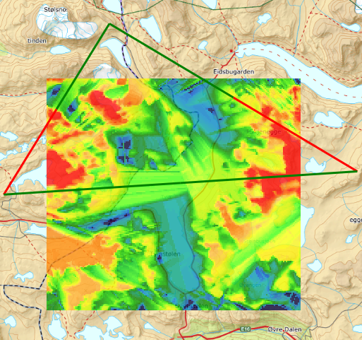
The resulting chart should look like this.
Every pixel in this chart shows the largest predicted signal strength received from any of the 3 participating units. To show individual contributions or contributions from a subset only, turn off the Visible property of all other units.
The position of each unit is indicated by the vertexes of the triangle drawn in green and red lines. The meaning of these lines, representing the state of mutual connectivity between units within a layer, will be discussed in the section on RadioConnectivity below.
In the above code example, it may appear strange that the TxPower of one of the units is adjusted after calculation is initiated. It could have been set before, but it is done so here to illustrate that parameters not representing wave frequency nor having anything to do with geometry or layer resolution may be adjusted a posteriori without the need of a full recalculation for the units affected. The reason is that the relative effect of signal amplification is independent of the predicted path loss between any two points - which solely depends upon wave frequency and the intermediate height profile. These effects can hence be accounted for on the fly. The parameters for which this is true are:
- TxPower
- TxGain
- RxGain
- (Antenna)
Antenna is a special case. It can be adjusted - with respect to azimuth and tilt, or replaced - i.e. with an antenna exhibiting a different radiation pattern. But it can not be _introduced_ without the need for recalculation. There is a difference between radio units with and without an explicit antenna as to the implementation of the calculation methods. If an antenna is present, the internal data structure produced will include ideal elevation angles and azimuths for every pixel. This information is not of any use otherwise, and hence not preserved nor calculated by default.
Process control
The unit.Calculate() method initiates (re)calculation of coverage contributions from that unit on a separate thread. The calling procedure may subscribe to notification on any of the following events.
- CalculationStarted
- CalculationCancelled
- CalculationComplete
The meaning of these events should not require much further explanation. Suffice it to say that the first one is simply a receipt that calculation has been initiated and is in progress. CalculationComplete is raised upon termination, successfully or not, whereas CalculationCancelled is raised upon premature cancellation - which will happen shortly after a call to unit.Cancel()
Processing time
Several factors determine the time needed to complete a single coverage calculation. Obviously the size of the area is important. Not so much the geographical extent of the assigned CoverageArea, rather that size measured in number of pixels - where pixel size is directly determined by the Resolution parameter of the layer. The application should be prepared to select a coarser pixel size the larger the area, as a rule of thumb. But this is also a simplification. What really matters is the number of pixels along a portion of the area boundary and the mean distance from any such pixel to the transmitter (also measured in pixels). The portion in question depends on the position of the transmitter with respect to its coverage area. Imagine a transmitter located south-west of a geographical rectangle. The set of rays scanning the northern and eastern edges of that rectangle will by necessity also have scanned the interior. Hence, the number of such rays times their average length (in pixels) is roughly proportional to processing time.
Resolution is bounded below by the resolution of available elevation data. At least for radio coverage in the VHF- and lower part of the UHF band, this is usually far better than what is actually needed to compute satisfactory predictions. With the diffraction models used for wave propagation, there is no rule that better resolution yields a more "true" or accurate result. Indeed, in addition to an inherent coarseness these models possess as approximations to true phenomena, there is a fundamental requirement that
wavelength << height differences along path < distance between identified obstacles.
RadioConnectivity
The set of radio units within a layer may be looked upon as nodes in a network. Independent of assigned coverage areas and indeed independent of coverage calculation as a whole, there is a process examining mutual connectivity between the units. For that purpose they are thought of as receivers as well as transmitters - dependent on the role assigned to them in that context. The possibilities, using the transmitterReceiver.Role - field are:
| Role | Description |
|---|---|
| [Off] | Unit does not participate |
| [TransmitterReceiver] | Unit has both transmit and receive capabilities. Transmissions do not disturb mutual connectivity among other units on the network. |
| [Transmitter] | Like above, without receive capabilities. |
| [Receiver] | Passive receiver |
| [Jammer] | Unit transmits only, and potentially disturbs reception on other units. |
Within the network, all units assigned as receivers - in any capacity, will by default accept signals from all transmitters - including jammers. There is a set of methods to mask out individual communication links. The application may then control the network layout directly, for instance to organize connections in a star-like pattern. These methods are accessed from the IRadioPorpagationLayer interface.
| Method/Property | Description |
|---|---|
| MaxDistance | Communication links between units separated by a distance beyond this value are ruled out. |
| SetConnectivityMask(...) | Mask or enable link between any two units. In the direction indicated by the parameter order only, or in both directions (default). |
| GetConnectivityMask(...) | Get current mask for a link |
| SetDefaultConnectivityMask(); | Set default mask, taking effect on all units subsequently added. |
For reception to be successful, received field strength must be above a minimum level. In addition, the ratio between this field strength and interference from any jammer must likewise be above a given level. These levels may be set individually for all units.
| Role | Description |
|---|---|
| [MinSignal] | Minimum field strength in dBm for reception to be possible. |
| [SNRatio] | Minimum signal to noise ratio for reception to be successful. |
RadioConnectivityView
There is a separate view for visualization of radio links. The constructor takes the IGeoContext- and the IRadioPropagtionProvider object as input.
IRadioConnectivityViewModel _rcViewModel;
var fac = new RadioConnectivityViewModelFactory(new RadioConnectivityViewFactory());
_rcViewModel = fac.New(_geoContext, _radioPropagationProvider);
The viewModel offers methods to adjust the appearance of connectivity lines. Default setting uses a green line to symbolize reception possible (or - in the case of the Freesight model - target is in sight from the observer), red line if reception is not possible and a white line if reception is not yet evaluated (or calculation not applicable - as will be the case using the Air Search Radar model). The connectivity lines shown in the picture above should thus be interpreted as follows. Signals from the northernmost unit can not be received by any of the two other units. (Which might have been expected since in the code example producing that result, transmitted power from the northernmost unit were set very low).
Connectivity Matrix Element
An application can also inspect a connectivity link directly, using a method available from the IRadioPropagationLayer interface:
INetworkConnectivity GetConnection(ITransmitterReceiver tx, ITransmitterReceiver rx);
The INetworkConnectivity object returned from this method offers the following fields:
| Field | Type | Description |
|---|---|---|
| Loss | double | Path loss in dB |
| TxAzimuth | double | Beam azimuth from tx in degrees, if tx has an Antenna |
| TxEffElevation | double | Beam effective elevation from rx in degrees, if tx has an Antenna |
| RxAzimuth | double | Beam azimuth from rx in degrees, if rx has an Antenna |
| RxEffElevation | double | Beam effective elevation from rx in degrees, if rx has an Antenna |
| Signal | double | Received signal intensity in dBm |
| Status | NetworkReceiverStatus | Reception status, one of ReceiverOff, ReceiverOK, ReceiverNotOK, ReceiverJammed, ReceiverUnknown |
Antennas
Optionally, radio units may be equipped with antennas having the property to focus, and hence amplify radiation in certain directions. Signals in unwanted directions are attenuated accordingly. At the receiver end, the effect is likewise - due to a larger aperture in certain directions compared to the isotropic point.
By default radio units do not have antennas. Indeed, the imaginary unit playing the part of receiver for coverage calculations has not even a fixed location, and it may be reasonably assumed that for any location within the coverage area and for the sake of predictions, the receiver antenna might be adjusted to optimize signal reception - although to do so at a given point for every direction simultaneously is of course unattainable. In coverage predictions it is the effect of antennas on the transmitter side that will be accounted for. For radio links and mutual connectivity between units, the presence of an antenna will be accounted for at the receiver end as well.
Antenna patterns
Introducing an Antenna requires a method to retrieve its gain distribution across the full surface of its aperture. This distribution is equipment specific only, and common to all antennas of the same type, independent of their individual location or adjustment in terms of tilt and azimuth. For this purpose, IRadioPropagation supports a register for antenna types and their associated gain distributions. The code lines below show the three methods provided. The first one adds a new antenna type to the register, the second retrieves the gain distribution given antenna type, and the last simply lists antenna types registered.
RegisterAntennaType(string antennaType, IAntennaGainDistribution gainDistribution);
IAntennaGainDistribution GetGainDistribution(string antennaType);
IEnumerable<string> GetRegisteredAntennaTypes();
[IAntennaGainDstribution] contains one function only, the one returning nominal antenna gain given frequency and a surface direction in terms of polar coordinates.
double Gain(double frequency, double theta, double phi);
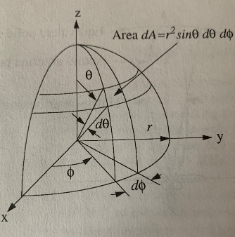
Frequency is assumed to be in MHz. Theta is in the range -90 to 90 degrees, and with respect to the x-y plane - not the z axis as in the figure below. Phi is in the range -180 to 180 degrees. The x axis corresponds to the antenna front.
Antenna deployment
Antennas are deployed by assignment to radio units, as in this code example:
//Create
var antenna = new Antenna()
{
Type = "some_antenna_type",
GainDistribution = _radioPropagationProvider.GetGainDistribution("some_antenna_type")
};

//Deploy
unit.Antenna = antenna;
antenna.Azimuth = 'bearing of antenna x - axis in degrees';
antenna.Tilt = 'angular elevation of antenna x - axis in degrees';
Antennas and coverage data
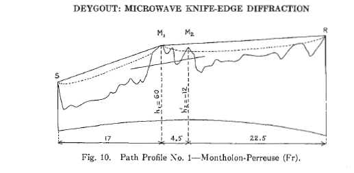
The drawing above shows a radiation path from S to R with two knife edges, and first Fresnel zones indicated. (M2 is a knife edge because it enters the Fresnel zone between M1 and R). A wave reaching any point between M1 and R must initially propagate between S and M1. These two points define the principal ray elevation for any subsequent point past M1. For points between S and M1, ray elevation gets less - in this case becoming negative for points sufficiently close to S. In order to account for radiation patterns, ray elevation and azimuth is calculated and kept for every pixel in the coverage chart. The reason for doing so is that these quantities depend on antenna heights and the intermediate terrain only, while independent on the antenna's radiation pattern and its orientation in terms of tilt and azimuth. Antenna adjustments with respect to these latter parameters may then be accounted for without a full recalculation.
There is a downside in terms of a more complex data structure and about twice the memory usage. It is recommended not to supply radio units with antenna objects if the antennas in question are more or less omnidirectional with respect to the intended coverage area.
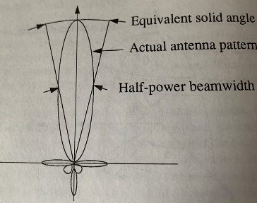
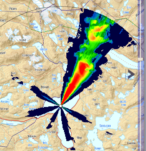
A coverage chart showing the effect of a strongly directional radiation pattern with some side lobes. Notice the way intensity increases towards the centre of the main lobe.
Feasibility Monitor
The Feasibility Monitor is an appended utility mechanism designed to solve a specific class of problems which can be summarised briefly as follows: Given a path and a geographical area, identify all feasible locations within that area suitable to set up a radio unit which then will be able to communicate with another radio unit being anywhere along the path. Both up- and downlink communication are required. Received signal strength in both directions above a given minimum is the feasibility criterion.
Two radio units is required. One assigned to be located within the search area, but with no fixed position. The other, likewise along the path. Calculation model and corresponding parameters are assigned as needed. The [IFeasibilityMonitor] interface exhibits the details. The code below shows an example:
var monitor = new FeasibilityMonitor(_radioPropagationProvider, _mapResources);
The parameters given are of type IRadioPropagationProvider and IMapResources respectively. The latter being needed for result display. In this respect, and a few others, the [Feasibility Monitor] behaves not unlike a RadioPropagationLayer - as shown below, although they are very different.
var model = _radioPropagationProvider.GetModelByName("VHF/UHF");
monitor.Model = model;
monitor.Legend = model.LegendInfo;
The area to be investigated may be set as a GeoRect - like here, or as a polygon - in which case the property to be used is SourceArea, not SourceRect. If SourceArea is set, it will override the SourceRect property.
monitor.SourceRect = some GeoRect;
Create a radiounit to operate within the source area and supply appropriate parameters, such as operating frequency. The position is immaterial. It is possible to use an already existing unit, if that is more convenient. There is now need for the unit to be attached to a [teleplanglobe.com/release/managed/interface_t_p_g_1_1_geo_framework_1_1_radio_propagation_1_1_provider_1_1_contracts_1_1_i_radio_propagation_layer.html RadioPropagationLayer].
monitor.SourceTxRx = new TransmitterReceiver(new GeoPos(0, 0));
monitor.SourceTxRx.Frequency = some_frequency_in_MHz;
Set a target path, and create a radio unit - along with necessary parameters to operate along that path. Again it is possible to use an existing unit, whether attached or not, and the position is immaterial.
monitor.TargetRoute = some IEnumerable<GeoPos>
monitor.TargetTxRx = new TransmitterReceiver(new GeoPos(0, 0));
monitor.TargetTxRx.Frequency = some_frequency_in_MHz;
Set a feasibility tolerance. A potential location within the source area is ruled out if received signal strength in any direction drops below that value as the second unit moves along the path.
monitor.MinSignal = -100.0;
Optionally change spatial resolution in meters (default = 270).
monitor.Resolution = some_resolution
Start monitoring
monitor.StartMonitoring();
Monitor control
Although not shown in the code example above, the calling procedure should subscribe to notification on some of the following events.
- MonitoringProgressChanged
- MonitoringComplete
- MonitoringCancelled
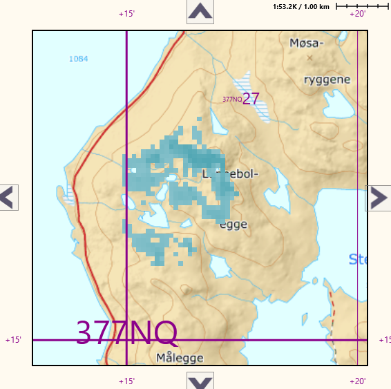
MonitoringProgressChanged will be raised on regular intervals during processing showing progress in percentage. Unless cancelled, MonitoringComplete will eventually be raised upon termination. Result will be displayed in a chart showing pixels at feasible locations according to the selected legend.
As to processing time, the same considerations apply as discussed in the Processing time section in regard to coverage calculations. Even more so, in view of the higher complexity in this case. If the search area is large, it is highly recommended to start with a coarse resolution initially, and then successively narrow the search.
