Symbols.xml is divided in seven parts contained inside the root element <symbolizations>.
Overall structure of the symbols.xml file:
<symbolization>
  <config\>
  <constants\>
  <colors\>
  <points\>
  <lines\>
  <areas\>
  <labels\>
</symbolization>
Symbolization
<symbolization> is the root node of the symbols.xml.
| Child element
|
Description
|
Properties
|
| config
|
Configuration settings used when building the map style.
|
O C
|
| constants
|
Constant definitions.
|
O C A
|
| colors
|
Color definitions.
|
O C A
|
| points
|
Point symbol definitions.
|
O C
|
| lines
|
Line symbol definitions.
|
O C
|
| areas
|
Area symbol definitions.
|
O C
|
| labels
|
Font characteristics and label rule definitions.
|
O C
|
Config
| Child element
|
Description
|
Properties
|
| yaxisdirection
|
Defines the direction of the yaxis for symbols/patterns.
|
O A
|
Yaxisdirection
| Attribute
|
Description
|
Properties
|
| value
|
up (origo in bottom left corner, y axis pointing up) or down (origon in top left corner, y axis pointing down). Default value is up.
|
|
Constants
| Child element
|
Description
|
Properties
|
| constant
|
Constant value needed for symbolization.
|
O R A
|
Constant
| Attribute
|
Description
|
Properties
|
| name
|
String that identifies the constant.
|
|
| value
|
The value of the constant.
|
|
Example:
<constants>
  <constant name="contour_interval" value="20"/>
</constants>
Colors
The <colors>node contain the color table information. This color table is referenced from the point, line, area and label sections of the symbol.xml file.
| Child element
|
Description
|
Properties
|
| color
|
Color value definition.
|
O R A
|
Color
| Attribute
|
Description
|
Properties
|
| Name
|
String that identifies the color.
|
|
| Rgba
|
value defining the red, green, blue and alpha values for the color.
|
|
Example:
<colors>
  <color name="black" rgba="0,0,0,255"/>
  <color name="black12" rgba="224,224,224,255"/>
  <color name="cyan" rgba="0,159,218,255"/>
  <color name="cyan4" rgba="242,252,252,255"/>
  <color name="white" rgba="255,255,255,255"/>
</colors>
Points
The <points> section of the feature symbolization file contains all point symbol definitions.
| Child element
|
Description
|
Properties
|
|
|
Configuration settings for points symbols.
|
O C
|
|
|
Point symbol definition.
|
O R C
|
Config
| Child element
|
Description
|
Properties
|
|
|
Scale factor applied to all pointsymbols and linepatterns used in symbolization. Local scale factors will be applied on top of this basescale value.
|
O A
|
|
|
Default root path to location of symbol/pattern files used in symbolization.
|
O A
|
Basescale
| Attribute
|
Description
|
Properties
|
| value
|
Scale factor. Default value is 1.0.
|
|
Defaultroot
| Attribute
|
Description
|
Properties
|
| path
|
Relative path to where the pointsymbol-files are located.
|
|
Point
The <point> blocks defines point symbols which are used either as a part of a complex line/area symbolization or as a single point map element. Point symbols can be rotated, offset and/or scaled.
Example:
<point>
  <sgname>Blue072_Obstruction</sgname>
  <origo type="centerx_y" y="0.25"/>
  <extent w="2.90" h="3.7"/>
  <scale value="0.7"/>
  <rotation offset="45.0"/>
</point>
| Child element
|
Description
|
Properties
|
| sgname
|
The name of the symbol graphic. This name is used when referencing the point definition from the script files or from other parts of the symbols.xml file.
|
|
|
|
The defined origo of the symbol (in mm).
|
A
|
|
|
The defined width and height of the symbol (in mm). Note: extent is only used when defining origo type "xy", "centerx_y" or "x_centery". X and y are then relative to the extent defined. Extent will not impact the size of the point symbol.
|
A
|
|
|
Scale factor used for modifying the symbol graphic size.
|
O A
|
|
|
Symbol rotation.
|
O A
|
Origo
| Attribute
|
Description
|
Properties
|
| type
|
How origo is defined. Valid values are: xy, center, centerx_y, x_centery.
|
|
| x
|
Origo x coordinate. Mandatory when value of type attribute is x_centery or xy.
|
|
| y
|
Origo y coordinate. Mandatory when value of type attribute is centerx_y or xy.
|
|
Extent
| Attribute
|
Description
|
Properties
|
| w
|
Width of the symbol graphic (in mm).
|
|
| h
|
Height of the symbol graphic (in mm).
|
|
Scale
| Attribute
|
Description
|
Properties
|
| value
|
Scale factor.
|
|
Rotation
| Attribute
|
Description
|
Properties
|
| offset
|
Rotation offset value in degrees.
|
|
Lines
The <lines> section of the file contains all line element definitions.
| Child element
|
Description
|
Properties
|
| config
|
Configuration settings for lines.
|
|
| line
|
Line element definition.
|
R C
|
Config
| Child element
|
Description
|
Properties
|
| basescale
|
Scale factor applied to all pointsymbols and linepatterns used in symbolization. Local scale factors will be applied on top of this basescale value.
|
O A
|
| defaultroot
|
Default root path to location of symbol/pattern files used in symbolization.
|
O A
|
Basescale
| Attribute
|
Description
|
Properties
|
| value
|
Scale factor. Default value is 1.0.
|
|
Defaultroot
| Attribute
|
Description
|
Properties
|
| path
|
Relative path to where the pointsymbol-, linepattern- and areapattern-files, are located.
|
|
Line
The <line> nodes defines lines which are used either as a part of a complex line/area symbolization, or as a single line element. Lines can be defined as one or more pens or as linepatterns. Point symbols can be attached to the line endpoints or centered.
Linepatterns and symbols must be available as .png-files.
Example (simple line):
<line>
  <sgname>Dk-Brown1815_0.4mmSolidLine</sgname>
  <pen style="solid" width="0.4" colorname="dkbrown1815"/>
</line>
Example (complex line):
<line>
  <sgname>LN_Dk-Brown1815_Cliff_High</sgname>
  <pen style="solid" width="0.2" colorname="dkbrown1815"/>
  <pen style="user" width="1.0" colorname="dkbrown1815" dashes="0.1,0.5" compoundarray="0.0,1.0"/>
</line>
Example (complex line with attached point symbols):
<line>
  <sgname>LN_Black_Bridge_DrawLift</sgname>
  <multiline spacing="1.3"/>
  <pen style="solid" width="0.3" colorname="black"/>
  <symbol name="Black_0.15mm-0.75mmLenWingTick" placement="start" rotoffset="0" yoffs="-0.65"/>
  <symbol name="Black_0.15mm-0.75mmLenWingTick" placement="start" rotoffset="90" yoffs="0.65"/>
  <symbol name="Black_0.15mm-0.75mmLenWingTick" placement="end" rotoffset="0" yoffs="-0.65"/>
  <symbol name="Black_0.15mm-0.75mmLenWingTick" placement="end" rotoffset="90" yoffs="0.65"/>
  <symbol name="Black_1.3mmCircleOpen" placement="mid"/>
</line>
Example (complex line using linepatterns):
<line>
  <multiline spacing="6.0"/>
  <sgname>LN_Dk-Brown1815_Cut_LargeGap</sgname>
  <linepattern name="Dk-Brown1815_Cut" type="png">
    <scale value="1.0"/>
    <ctrlpts start="0.0,0.5" end="1.0,0.5"/>
  </linepattern>
</line>
| Child element
|
Description
|
Properties
|
| sgname
|
The name of the symbol graphic. This name is used when referencing the point definition from the script files or from other parts of the symbols.xml file.
|
\
|
| pen
|
Defines a pen style for drawing.
|
O R A
|
| multiline
|
Defines a multiline (two parallell lines drawn). Only valid in combination with <pen>.
|
O A
|
| symbol
|
Defines a symbol to be drawn on the start- end- or center-point of a line. Only valid in combination with <pen>.
|
O A
|
| linepattern
|
Defines a patternfile to use when symbolizing.
|
O C A
|
Pen
| Attribute
|
Description
|
Properties
|
| style
|
Valid values are “solid†and “userâ€. The “user†style is useful when defining lines custom dash/dot spacing.
|
|
| width
|
Pen width.
|
O
|
| colorname
|
Pen color (defined in color table).
|
O
|
| dashes
|
Comma separated list of dash/space values used when creating custom dash/dot lines. Mandatory when style is set to user.
|
O
|
| compoundarray
|
Comma separated list of values to specify a compound pen. Can f.ex. be used in combination with the dashes attribute to draw a line with ticks on just one side. Values are in percent of the pen width.
|
O
|
Multiline
| Attribute
|
Description
|
Properties
|
| spacing
|
Spacing (in mm) between the parallell lines in a multiline.
|
O
|
Symbol
| Attribute
|
Description
|
Properties
|
| name
|
Name of the symbol graphic to be used in combination with the pen style. Should correspond to an existing sgname already defined in a <point> node.
|
O
|
| placement
|
Placement of the symbol on the line. Valid values are start, end and center.
|
O
|
| rotoffset
|
Rotation offset.
|
O
|
| xoffs
|
Offset in the X direction.
|
O
|
| yoffs
|
Offset in the Y direction.
|
O
|
Linepattern
| Attribute
|
Description
|
Properties
|
| name
|
Linepattern filename (only basename, no extension). Should be located at the path pointed to by the <defaultroot> node in the config section of the file.
|
|
| type
|
File extension
|
|
| Child element
|
Description
|
Properties
|
| scale
|
Scale factor used for modifying the filepattern size.
|
O A
|
| ctrlpts
|
Control points used to place the corners of the linepattern correctly.
|
O A
|
Scale
| Attribute
|
Description
|
Properties
|
| value
|
Scale factor.
|
O
|
Ctrlpts
| Attribute
|
Description
|
Properties
|
| start
|
X and Y coordinates specifying the start point of the linepattern.
|
O
|
| end
|
X and Y coordinates specifying the end point of the linepattern.
|
O
|
Areas
The <areas> section of the file (located on the level below the root node) contains all area symbol definitions.
| Child element
|
Description
|
Properties
|
| config
|
Configuration settings for areas.
|
|
| area
|
Area element definition.
|
R C
|
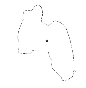
Figur 3: Example of complex area style
Config
| Child element
|
Description
|
Properties
|
| defaultroot
|
Default root path to location of symbol/pattern files used in symbolization.
|
O A
|
Defaultroot
| Attribute
|
Description
|
Properties
|
| path
|
Relative path to where the pointsymbol-, linepattern- and areapattern-files, are located.
|
|
Area
Areas can be symbolized with outlines, fill patterns/textures and point symbols attached. Textures/brushbitmaps must be available as .png files.
Example:
<area>
  <sgname>AR_Black_Mine_Abandoned</sgname>
  <outline linename="Black_0.2mm-2mmLenDash-0.5mmGapLine"/>
  <symbol name="Black_PickAxeShovel180" placement="center"/>
</area>
| Child element
|
Description
|
Properties
|
| sgname
|
The name of the symbol graphic. This name is used when referencing the point definition from the script files or from other parts of the symbols.xml file.
|
O
|
| outline
|
Definition of the area outline.
|
O A
|
| brush
|
Definition of the area brush.
|
O A
|
| symbol
|
Defines a symbol to be drawn on the approximate top or center of an area.
|
O R A
|
| brushbitmap
|
Defines a fill pattern bitmap for the brush.
|
O A
|
Outline
| Attribute
|
Description
|
Properties
|
| linename
|
References a line definition to use as outline.
|
|
Brush
| Attribute
|
Description
|
Properties
|
| style
|
Brush style. Valid values are [solid, hatched].
|
|
| hatch
|
Hatch pattern. Mandatory if style is hatched. Valid values are [bdiagonal, cross, diagcross, fdiagonal, horizontal, vertical].
|
O
|
| colorname
|
Brush color (defined in color table).
|
O
|
Symbol
| Attribute
|
Description
|
Properties
|
| name
|
Name of the symbol graphic to be used in combination with the pen style. Should correspond to an existing sgname already defined in a <point> node.
|
O
|
| placement
|
Placement of the symbol on the line. Valid values are [top, center].
|
O
|
| rotoffset
|
Rotation offset.
|
O
|
| xoffs
|
Offset in the X direction.
|
O
|
| yoffs
|
Offset in the Y direction.
|
O
|
Brushbitmap
| Attribute
|
Description
|
Properties
|
| name
|
Bitmapbrush filename (only basename, no extension). Should be located at the path pointed to by the <defaultroot> node in the config section of the file.
|
|
Labels
The <labels> section of the symbols.xml allows the creation of complex labels for display in MARIA. Labels can be based on primitive attributes. It is possible to define conditional labelling as demonstrated in the example below.
This section also contains the font descriptions used in label rules and label filters.
Example:
<labelrule name="R000030">
  <label name="R000030_1">
    <condition oper="and">
      <condition oper="noteq" field="HWT" value="5"/>
      <condition oper="noteq" field="HWT" value="6"/>
    </condition>
    <item type="attrib" characteristics="1" value="NAM"/>
  </label>
  <label name="R000030_2">
    <condition oper="equal" field="HWT" value="6"/>
    <item type="string" characteristics="1" value="Minaret"/>
  </label>
  <label name="R000030_3">
    <condition oper="equal" field="HWT" value="5"/>
    <item type="string" characteristics="1" value="Marabout"/>
  </label>
</labelrule>
| Child element
|
Description
|
Properties
|
| characteristics
|
Font characteristics.
|
C A
|
| labelrule
|
Label rule definition.
|
R C A
|
| labelfilter
|
Label filter definition.
|
R C A
|
Characteristics
Defines font characteristics for use in labelrules.
Example:
<characteristics fontname="Calibri" scale="1">
  <item name="Black" id="1" colorname="Black" size="6"/>
  <item name="Red" id="2" colorname="Red" style="condensed" size="8"/>
  <item name="Bold" id="3" colorname="Black" size="6" bold="true" italics="true"/>
  <item name="Dynamic" id="4" colorname="Black" size="6" levelstosizes="7,8,8,10,9,10,10,10,11,12"/>
</characteristics>
| Attribute
|
Description
|
Properties
|
| fontname
|
Name of default font to use for labels.
|
O
|
| scale
|
Default scale factor.
|
O
|
| Child element
|
Description
|
Properties
|
| item
|
Font properties. Can be referenced by id from label rules.
|
R A
|
Item
| Attribute
|
Description
|
Properties
|
| id
|
Unique identifier for font description.
|
|
| fontname
|
Name of font used in characteristic.
|
O
|
| colorname
|
Font color (defined in color table).
|
O
|
| style
|
Font style. Valid values are [condensed, light condensed, regular].
|
O
|
| bold
|
True if text should be in bold.
|
O
|
| italics
|
True if text should be in italics.
|
O
|
| size
|
Font size, point (pt) size of the text string.
|
O
|
| case
|
Indication of capitalization. Valid values are [upper, lower, mixed]. Not implemented.
|
O
|
| scale
|
Scale factor.
|
O
|
| outline
|
Draw labels with thin outline. Default value is true. Implemented since MARIA GDK 3.1.
|
O
|
| outlinecolor
|
Outline color (defined in color table). Default outline color is white. Implementend since MARIA GDK 3.1
|
O
|
| levelstosizes
|
Dynamic fontsizing.
|
O
|
Levelstosizes
Use this attribute to control dynamic scaling of fonts by specifying a comma separated list of level and fontsize-pairs [level,size]. Note that gaps in the level-range will default to the fontsize specified in 'size'. Levels lower than the minimum level defined will use size defined for the minimum level. Levels above the maximum level defined will use the size defined for the maximum level.
Example:
<item name="example" levelstosizes="7,10,8,12,9,12,10,12,11,12,12,15"/>
Example above defines fontsizes for levels 7 through 12. Level 7 (and 1-6) uses fontsize 10. Level 8-11 uses fontsize 12. Level 12 (and all successive levels) uses fontsize 15.
Labelrule
Example:
<labelrule name="R000024">
  <label>
    <condition oper="equal" field="TYP" value="5"/>
    <item type="attrib" characteristics="3" value="NAM"/>
    <item type="string" characteristics="3" value="Zoo"/>
  </label>
</labelrule>
| Attribute
|
Description
|
Properties
|
| name
|
Name that identifies the labelrule. Can be referenced from the attribute based script files.
|
|
| Child element
|
Description
|
Properties
|
| label
|
Label description block.
|
R C A
|
Label
| Child element
|
Description
|
Properties
|
| condition
|
Rule condition.
|
O R C A
|
| item
|
Text description.
|
R A
|
Condition
| Child element
|
Description
|
Properties
|
| condition
|
Rule condition.
|
O R C A
|
| Attribute
|
Description
|
Properties
|
| oper
|
Condition operator. Can both be used as a logical operator with values [and, or], or a compare operator with values [equal, noteq, less, lesseq, grt, grteq, in, mod, undefined].
|
|
| field
|
Attribute field.
|
|
| value
|
Attribute value.
|
|
| remainder
|
Remainder value to be used together with "mod"-operator.
|
O
|
Item
| Attribute
|
Description
|
Properties
|
| type
|
Text item type. Valid values are [attrib, string].
|
|
| characteristics
|
Font characteristics identifier.
|
|
| value
|
Text to display in label. If type is attrib, the value is set to the name of the attribute text should be collected from.
|
|
| break
|
If true, linebreak will be inserted succeeding this text item.
|
|
Labelfilter
Apply a labelfilter to remove unwanted text in the map.
Example:
<labelfilter>
  <suppress value="UNK"/>
  <suppress value="EMPTY"/>
  <suppress value="Unknown"/>
  <suppress value="Other"/>
</labelfilter>
| Child element
|
Description
|
Properties
|
| suppress
|
Text value to suppress when drawing labels in map.
|
A R
|
Suppress
| Attribute
|
Description
|
Properties
|
| value
|
Text value.
|
|
